Projects

MONITORING YOUR MODULATION

I’ve been doing a bit of AM operating of late.  This vintage mode if fun to operate and sounds great when the band conditions aren’t too noisy.  I’ve also been repairing and tinkering with some old transmitters as mentioned in other posts.  One of the highest pursuits of the AM op is to achieve great audio.  Many will go to great lengths to buy studio rack gear with pre-amps, compressors, limiters, and EQ.  Top off all this hamsexy rack gear with a big old boom mic!

The other part of the equation is to properly adjust the audio modulation.  It’s not as simple as watching the ALC meter like on SSB (although it does help).  A first step is to look at the RF waveform on an oscilloscope.  You want to verify that the wave isn’t flat topping.  A modulation monitor can be used to view the modulation percentage.  Combine these two together and you get the AMM-SD1 by Radio Engineering Associates.  This slick device connects into the feedline and runs in software on the computer.  It’s pretty much real-time display shows the RF waveform and the negative and positive modulation percentage peaks.

Seemed like this might be a worthwhile investment for the shack…like I even need an excuse to by cool shack gear!  So far it’s confirmed that my AM audio is clean with positive peaks over 120% and negative peaks right at 100%.  Right about where it needs to be.  I’ve also used it to detect that the Ranger II I’m working on is in need of further inspection.  The positive peaks only hit about 40% before the stopping point when negative peaks hit 100%.  I never would have found that without the monitor unless trying to make a contact and some OM tells me my signal is crap.

This monitor has already proven to be an asset to my radio operation.  I just wanted to share it with my followers and encourage people to give AM a try if you like a little more than UR 59 OM, QRZ.  There are frequent AM operating events throughout the year, so there’s no excuse not to lay down some carrier and chat it up.

Categories: Activities, Amateur Radio, Projects, Uncategorized | Tags: , , , , , , | Leave a comment

TALE OF TWO RANGERS

I’ve been taking a bit of a break on the Viking II project I mentioned in the last post.  Multiple projects always seem to make their way into the shack and cause me distraction.  I had an offer come up I couldn’t refuse, and so, had to make room on the bench.  My friend Ward K8FD has four Johnson Viking Rangers in his collection.  Two are the original model Ranger and the other two are Range II models.  He wants to have the best one of each model repaired and keep it for himself.  I get to keep the other two for my collection as payment for making all the appropriate repairs.  Sounded like a good deal to me.  Fortunately, Ward already purchased a couple nice capacitor repair kits and some missing hardware from Nationwide Radio and Equipment Sales.

The new parts are quite a bit smaller than the original parts so it wasn’t too much trouble fitting them into the chassis.  Several of the old caps were pretty crusty and would certainly would be an issue if they hadn’t already failed.  I didn’t want to take any chances so I went straight to making repairs instead of giving an initial test.  Along the way, I also tested the tubes and found a couple bad and wrong spec.  I was able to do a swap-a-roo since there were four transmitters in the shack!

Repairs have been pretty straight forward so far.  Considering it didn’t work at all when I started, making even a little power is success.  Power output stays around 25-30 watts AM and CW.  I’ve found it to be pretty easy to tune up compared to other tube rigs I’ve tried.  It also seems to be pretty forgiving and tolerant of my slow tune-up, which is nice…I have smoked components before from persistent mis-tuned conditions.

This is actually a 160-6m transmitter which is kinda cool for such an old rig.  I suspect most people really only operate them on 80 and 40m if running AM.  Maybe other bands on CW I suppose.  The dial reads within about 12 kHz which isn’t too bad.  Looking forward to installing it back into the cabinet and giving it a try on the air.

Categories: Activities, Amateur Radio, Projects | Tags: , , , , , , | Leave a comment

VIKING II: DISASSEMBLY

IMAG1621
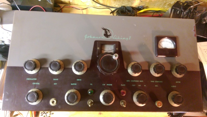
The first stage of fixing up this old transmitter is disassembly.  When Johnson built their gear they certainly didn’t spare the fasteners.  This thing is held together by a ton of slotted head screws.  Took forever to remove them all.  Fortunately, the cabinet came apart really easy.  The hardest part was removing the front

IMAG1622

face.  Once I had all the pieces separated I got busy with a bottle of Formula 409 cleaner and paper towels.  This works pretty well on most stuff.  I also used a tooth brush to really scrub the parts that had a course exterior finish.  It didn’t work miracles, but for a transmitter nearing 70 yrs old it’s not too bad.

IMAG1643
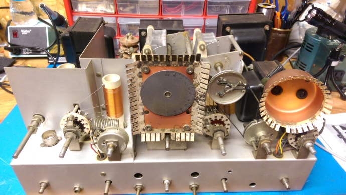
I now have access to the chassis of the beast.  I’m impressed with the overall design, construction, layout, and quality.  You can really tell these were built to last.  The top side will definitely need some scrubbing, but I don’t see rust or corrosion.  Of specific interest is the ganged, gear-driven variable inductor/capacitor tuning unit.  Not only is it exceedingly grungy, but it’s not operating correctly.  I believe this is the only item of concern up top.

IMAG1644                                  IMAG1645

The bottom of the chassis also looks as expected.  A little dusty and some spider webs, but pretty clean.  Fortunately, no surprises down there.  I will have many electrolytic and waxy caps that will need replaced.  Since I don’t own a leakage tester I’ll just have to assume they’re all suspect at this age.  The worst thing is to let electronics just sit.  Even very old components will continue to perform for decades if they’re just used regularly.  IMAG1618I’ll also have to do some checks on the resistors as they’ve probably drifted, too.  Some components are more critical than others depending on the particular circuit.  This will just take some time to research the usual suspects and start ordering.


Fortunately, Johnson made a lot of these transmitters.  I’d like to purchase a manual reprint but was able to easily find a PDF on the BAMA website.  I’ve found them to be very helpful for everything except Heathkit (because of copyright licensing).  I’ve had good luck purchasing reprints from Manualman and others.

IMAG1620Here’s a pic of this big honkin’ oil filled cap.  No reason to include it except it’s cool.  Just another example of the quality put into these rigs.  Hoping to get the chassis all cleaned up and the roller inductor functional again.  That will complete the first phase of the project.  I think the next part will be more fun.  I like working with components better than cleaning stuff up.  Stay tuned.

Categories: Activities, Amateur Radio, Projects, Viking II | Tags: , , , , , , | 1 Comment

BITX PROJECT

IMAG1637

Most hams who know me, know that I love to tinker and work on projects.  Sometimes they even work out in the end.  So begins this one.  I’m an avid follower of the Soldersmoke podcast and website.  Bill Meara N2CQR and Pete Juliano N6QW host a monthly podcast all about QRP and radio homebrew.  Their inspiration has given me the courage to begin and successfully complete several projects.  The Michigan Mighty Mite is a good example.  One of their homebrew heroes is Ashhar Farhan VU2ESE who invented the BITX transceiver 14 years ago.  Last year they reported that he’s selling the board fully constructed and tested.  All you need to do is find a suitable enclosure and attach the peripherals.  At the $45 price point it’s hard to beat as a development platform.  The basic radio can be upgraded to stabilize the analog VFO or even improved by adding a DDS or PLL VFO quite easily.  Low pass output filters can be added to take it from a 40m monobander to all band operation.  I couldn’t resist!

IMAG1638
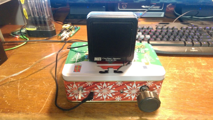
With the circuit fully complete, this amounted to a one day project to get the basic assembly done.  I found a suitable Christmas tin for a cabinet.  The majority of my time was spent laying out and marking holes for the board standoffs and all the jacks and pots to be connected.  It’s not exceedingly elegant but I IMAG1639was able to accomplish it all with a hand drill, pliars, and a couple wrenches.  I chose the metal enclosure because I thought It might provide good shielding.  Eventually I’ll probably add a small fan and punch some holes for ventilation.  There should also be enough room to add an Arduino, DDS or PLL board, and cool LCD display.  I think it would make a perfect radio for portable operation with a battery and 40m dipole at the park.

IMAG1640

I wanted to include a couple shots of the innards.  Everything came included with the kit, including the wiring pigtails to attach to the board headers.  Pretty straight forward assembly.  The HF Signals webpage has all the technical info, assembly

IMAG1641instructions, reference materials, and purchase info.  The product is sourced and shipped out of India and constructed by a local women’s collective that helps provide skills and jobs.  They typically arrive in less than a month.  Not bad turn around time.  Easy ordering with Paypal.

So here it is with a couple knobs out of the junk drawer.  I trialed it on the bench and it plays great, minus the drift.  Even that settles down after about 15 minutes.  Crisp, clear analog audio…but you have to ride the AF gain what for having no AGC.  I bet you could probably hack that into the circuit pretty easy, too.  I could generally hear just about anything I could copy on the Flex-5000, so that says something about the sensitivity.  This was a fun and functional one day project with only minimal soldering required.  Looking forward to doing some more hacking on this one!  Will try to produce a companion post with a little video production for everyone playing along at home.  73 all.

IMAG1642

Categories: Activities, Amateur Radio, Projects | Tags: , , , , , | Leave a comment

TIME TO BEGIN AGAIN: VIKING II

It appears as though I haven’t made a post in over a year.  Time flies when you’re having fun…or extremely busy.  It’s time to start a new project.  In doing so, it might be fun to document the progress here in cyberspace (does anyone even still say that).  It’s a good way to keep track of what’s been done, and also share with friends.  Often times it might also be a topic of interest to many others outside your local chums.  My posts on the ARD 230 project sure generated a lot of feedback from other owners.  I received inquiries from hams as far as Spain and Germany!  Strap in for the ride…here it begins.

IMAG1421
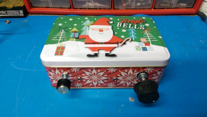
I got energized to try something new after participation in the AM Rally early this spring.  I’ve always been interested in vintage radio and the roots of our hobby.  While CW holds the crown as oldest mode, AM isn’t too far behind.  Many modern and vintage radios will operate AM, but I get a kick out of using vintage gear to operate a vintage mode.  My lash-up for the event was a Heathkit DX-60A transmitter with the matching HG-10 VFO and Astatic D-104 mic.  Classic 60’s and good for about 55W PEP.  The receIMAG1354iver was a Yaesu FRdx-400.  Early 70’s production, and it did pretty well for me, too.  I didn’t yet have a dowkey relay so all the switching was done manually.  Let me tell you, that’s a lot of work just to complete an exchange!  My time was limited, and I made only one contact but I think the hook was set.  Time to finally breath new life into this old gear that’s been sitting around cluttering up my shack.

TeJohnson-logo-1n years ago I purchased a Johnson Viking II transmitter from a good friend and elmer Joel, K2LYC (now SK).  I also came home with several other vintage pieces from his extensive collection, but that will become the subject matter of many future posts.  The intent was to setup an AM station (Studio B) to accompany my then-modern Icom IC-756 station (Studio A).  Somehow a decade passed away and, sadly, so did Joel.  I guess I feel like I owe it to him to get this stuff playing again.  So, it begins with the transmitter.  I’m going to start there because usually they’re simpler.  I’ve also had pretty good success fixing others.  Fortunately, there’s loads of info available at my fingertips.  This is the intro so I’m not going too deep.  My plan is to remove the chassis from the cabinet for overall cleaning and inspection.  I’ll replace any faulty components and perform only the mods that are proven and considered best practice.  No total restoration needed.  I’m sure every scratch and scrape tells a story.  It’ll never be a mint specimen, just an honest workhorse.  Eventually it’ll pair with my Collins 75A-3 (which will probably be the next project).  But you see I’m already ahead of myself.  Next post will start getting into the real heart of the job.  73!IMAG1621

Categories: Activities, Amateur Radio, Projects, Viking II | Tags: , , , , , , , | Leave a comment

THE MICHIGAN (INDY) MIGHTY MITE


Most of my ham friends know I’ve been a devoted listener of the SolderSmoke podcast for some time.  Bill Meara N2CQR and Pete Juliano N6QW make a great team discussing the building and operating of all manner of homebrew, boatanchor, and QRP gear.  Their enthusiasm is obvious and they really give the listener a sense of confidence that it just might be possible to really build something yourself in this modern age.

Building components and constructing circuits is to me the essence of ham radio.  I’ve built small kits like the N0XAS Pico Keyer from Ham Gadgets and similar odds and ends, but never any “real” ham gear.  I’m kinda like the average Joe that watches the home remodeling show on TV and thinks it’s cool to restore the 100 year old house, but lives in a newer house with little maintenance.  It all sounds glorious, but you have no idea where to start.

Enter the Michigan Mighty Mite.  This simple transmitter requires only seven components and produces around 500 mW RF output.  To up the ante Bill sent out the necessary 3.579 MHz colorburst crystal for free to anyone who emailed him a request and promised to use it.  Pete built the circuit and added some pro tips of his own on MMM construction on the blog.  Now this seemed to be a project I could handle!  I fired off an email in short order.

My crystal got torqued by the USPS!

My crystal got torqued by the USPS!

What arrived was something of a disappointment.  Evidently USPS sorts mail with a steam roller.  My precious crystal looked like momma worked it over with a rolling pin!  This depressed me enough that I delayed building the transmitter for some time.  I panicked and purchased a whole bag of crystals, just to be safe.  Eventually I turned up some magnet wire, a pill bottle and the necessary capacitor and resistors.  The remaining air variable cap was ordered from Amazon.  Turns out they have all manor of useful materials, who knew?

First winding with tap.

First winding with tap.

The hardest part was winding the coil.  That wasn’t too bad, though.  I held it together with tape.  Everything was assembled on a bread board for trial.  I must admit to being overjoyed when I saw the visual waveform on the PowerSDR panafall display of my Flex-5000A main shack radio.  So much so, that I ran through the house calling for my YL, KC9TAH.  She was in the shower

Second winding over the first goes to antenna and ground.

Second winding over the first goes to antenna and ground.

and thought I’d cut off a finger or something while in the mad scientist lair.  Much to her dismay, it was only a nasty CW signal emanating from the Flex speaker.  She did humor me by going out to see the marvelous project before asking me what I was going to fix for lunch.

So where do I go from here?  I have a small piece of perfboard on the bench.  I guess I should assemble it on that in a proper arrangement.  My friend Brian KB9BVN has requested a QSO but I’ll need to build a low pass filter to knock down the harmonics.  No sense of incurring the wrath of the FCC and homebrewers everywhere.  My next project is a small regen receiver and the Ugly Weekender and Ugly Weekender II combo.  Both of these come from old issue of QST.  I have the circuit boards from Far Circuits and plan to build them with the boys.  Might as well infect the next generation with a case of “the knack” if at all possible.

Join the revolution!

Join the revolution!

Categories: Activities, Amateur Radio, Projects | Tags: , , , , | 2 Comments

POWER SUPPLY FOLLOW UP

Well, the HV power supply seems to be humming along nicely.  The meter on the control head displays 2500 VDC which is probably about right considering my line voltage in the shack (248 VAC).  As promised, I measured all the resistors that were removed from the supply and noted their values.  I also noted their specified range based on the five percent tolerance value.  As expected, not a one was in spec.  I’m not sure that this really makes much difference as the power supply isn’t exactly a calibrated circuit, but it would be silly not to replace them while refurbing the supply.  They’re inexpensive and easy to replace.  I substituted metal film resistors of the same value and power rating rather than the original carbon composition.

I haven’t had a single issue at all with breakers tripping on the amp or sub panel since making the repairs.  I’ll conclude that it was definitely a faulty filter cap (or maybe several).   It uses six 240 uF 450V computer grade electrolytics in series for a total of 40 uF DC filtering goodness.  I don’t have a way to test them at this time to determine their values.   Actually, I don’t even have them anymore.  The neighbor kid (Jacob KC9ZYV) wanted them (and also the caps from the Amp Supply LK-500 NT power supply I refurbed last year).  He mentioned something about a rail gun…future mad scientist at work!

I recorded the values for everyone on a pad of genuine Purdue green engineering graph paper.  I still have nearly a full pad of this stuff after nearly 20 years.  I wasn’t an engineering student!  I hope you all find the info interesting.  The next order of business for the amp is to synch the DC drive system with the Tune and Load air variable caps in the RF deck.  Then I can calibrate them all for roughly every 100 KHz of each band and let the amp auto tune itself!

Check out how far some of the resistor values have changed.

Check out how far some of the resistor values have changed.

Categories: Activities, Amateur Radio, Projects | Tags: , , , , , | Leave a comment

ARD MODEL 230A POWER SUPPLY


Another phase in the amplifier rebuild is now complete.  Thanks to the large chassis I was able to remove the transformer and HV power supply with little effort.  It’s a lot lighter with that monster Peter Dahl hypersil removed.  Only a moderate amount of contortion was required to extricate the power supply assembly through the bottom opening.  The rebuild went pretty straight forward.  Fortunately, power supplies are not incredibly complicated beasts.  The main issue I had was a couple traces came loose from the circuit board as I was de-soldering.  Thankfully, I was able to get them all back down into position when the new components were installed.  The solder is holding them in place.

Grungy bits removed from circuit board.

Grungy bits removed from circuit board.

Components removed were: six 240 uF computer grade electrolytics, twelve 150K 2W resistors, one 1M 2W resistor, and five .01 uF disk caps.  The other components looked to be in pretty good shape.  The board was pretty grungy so I took some time to wipe it all down with alcohol before soldering it back together.  I made only one component substitution.  The original carbon composition resistors were replaced with metal film resistors of the same value and power rating.

The HV power supply is designed to provide 2300 VDC at 1.0 A.  There is a total of 40 uF of capacitance for filtering the DC.  My original problem was the circuit breaker on the chassis and/or the circuit breaker in the sub panel would trip when I powered up the amp.  This would happen either right after the power switch was flipped or as the step-start circuit dropped out.  On occasional times when it didn’t trip, it would run for some time and then trip suddenly.  This was especially annoying!

I’m pleased to report I’ve successfully tested the supply several times now and it seems to be working great.  The meter on the control head shows a steady 2500 VDC.  Initial load testing with low drive (up to 35 W) has provided up to 700 W out into the dummy load.  If everything proves to be linear, as it should be, then I should easily see legal limit with under 100 W drive from the exciter (in this case a Flex-5000A).  This is also without getting Plate and Load caps fully peaked in manual tune mode.

The gear motor drives are not properly synced right now.  They should be turning from 0-180 degrees as shown on the control head indicator.  Right now one is and the other just moves from roughly half-meshed to half-meshed on the other side, never getting fully meshed.  Getting them properly adjusted will be my next project.  This portion will switch from electrical to mechanical technique.  Good thing I do this kind of stuff in the real world!

Categories: Amateur Radio, Projects | Tags: , , , , , | Leave a comment

ARD MODEL 230A BACK STORY

ICOM ARD BrochureThrough the magic of the internet, namely Google, I’ve been able to learn a little more about the Advanced Radio Devices Model 230A.  I’ve been in contact via email with the ham that owned ARD and he’s been kind enough to share with me many details about the company.  So now I’ll be able to share the info with the rest of the ham community.

Advanced Radio Devices was owned by Bob Sullivan W0YVA.  It grew out of a previous company, Technical Services and Manufacturing.  Originally they provided product design and manufacturing services.  The lead engineer was Chuck White.  I don’t know if he was a ham or not.  They later changed the name after investigating HF amplifier design and production.  The company was in business from the 1980’s into the mid 1990’s.ARD dealer listing

Various models of amplifier were produced by ARD.  Models 230A, 230AX, 230C, 230CX were sold both stateside and export, as well as government contract sales.  The two models of chief interest to amateurs would be the 230A with two 3CX800 tubes for 1500 watts continuous output and the 230C with three 3CX800’s for 2250 watts continuous output.  There aren’t any specific sales records, but Bob believes they sold about 100 230A’s and maybe only 25 230C’s!

By 1989 they had established a world wide dealer network for the amp.  Many of these are big name companies still in business.

Dayton AdvertThey also had a booth at the Dayton Hamvention that same year.  With the exception of military equipment, this was the only truly automatic linear amp on the market.  This was an opportunity to present the revolutionary new amplifier to the ham community.  So much so, that it even attracted the attention of ICOM!  There were several months of company negotiations which were to culminate in the production of a genuine ICOM badged super amp.  In the end, ICOM backed out which probably led to the eventual demise of ARD, being it was a pretty small company.

Dayton Hamvention Booth 1989

Dayton Hamvention Booth 1989

I’m happy to report that Bob Sullivan is still an active ham.  His QRZ.com bio page is quite nice and informative.  You can view it here.  He also has a personal webpage which showcases his love of ham radio as well as other interesting hobbies.  Click here for Bob’s personal page.  A lot of good information here for the ham enthusiast.  You can view his rundown on the ARD-230 from here.  Next step for me is to order parts and get busy with the soldering iron.  All for now.

Categories: Amateur Radio, Projects | Tags: , , , , , | 1 Comment

ARD MODEL 230 VIDEO OVERVIEW

I just finished making a video that shows the ARD 230A on the bench.  I go over some of the basics about the amp and a little history.  I’m still doing research and will eventually devote a whole page here on the blog site to this rare beast of QRO proportions.  Next step is to start the tear down and order parts.  Hope you all find this informative.

Categories: Amateur Radio, Projects | Tags: , , , , , | 4 Comments

Create a free website or blog at WordPress.com.